Engine Timing - What's wrong?

This forum is about the Fordson Dexta, Super Dexta and Petrol Dexta.
Post Reply
Bensdexta
True Blue
Posts: 2666
Joined: Mon Sep 15, 2008 12:59 pm
Location: N Wales

Engine Timing - What's wrong?

Post by Bensdexta »

Whilst checking the timing of my engine, which has been rebuilt recently by an engine shop, I observed the following:

I set the Idler Gearwheel Timing line, marked in white in the photo below, at the Top Dead Centre Position (according to the manual).
Image

However the Flywheel does not appear to be in the TDC position, see below.
Image
According to the manual the 7th hole should be at the bottom instead of displaced anti-clockwise by about 68degs. The Flywheel appears to be fitted correctly with the 7th hole aligned with the matching extra hole in the crankshaft.

Is something wrong?

Your advice appreciated. :wink:

Ben

commander
True Blue
Posts: 115
Joined: Fri Jun 27, 2008 10:59 pm
Location: Sharon South Carolina

Post by commander »

Ben, there are three timing marks on that idler gear, one for the camshaft, one for the crank, one for the pump. You may be looking at the wrong one.

There should be a tdc mark on the flywheel, normally visible through the small swing away plate on the left side of the clutch housing. Of course if you have tractor split, this isn't going to help.
You want to find tdc for #1 cylinder on it's compression stroke. If you pull the timing cover, you can turn the crank until all the marks line up (may take several turns).
Jack

Bensdexta
True Blue
Posts: 2666
Joined: Mon Sep 15, 2008 12:59 pm
Location: N Wales

Post by Bensdexta »

Jack,
commander wrote:there are three timing marks on that idler gear, one for the camshaft, one for the crank, one for the pump. You may be looking at the wrong one.
Good point! I have been assuming that the mark with the white painted line is for the fuel pump, as I thought that was what the engine shop said. I can't turn the engine over just now, as I haven't got a big enough socket for the pulley nut (see my other post of today), so haven't been able to check the other marks, which clearly I need to do.
commander wrote:There should be a tdc mark on the flywheel, normally visible through the small swing away plate on the left side of the clutch housing. Of course if you have tractor split, this isn't going to help.
I do have the tractor split, but can estimate the approx postion of TDC against the engine's rear back plate, by measuring across from the clutch housing. Also the 7th hole in the flywheel should be at the bottom for TDC.
commander wrote:You want to find tdc for #1 cylinder on it's compression stroke. If you pull the timing cover, you can turn the crank until all the marks line up (may take several turns).
I'm a bit daunted by pulling the cover - doesn't that mean removing the pulley or can I peak in without removing the pulley?

Many thanks for your help,
Have a happy Easter,
Ben

commander
True Blue
Posts: 115
Joined: Fri Jun 27, 2008 10:59 pm
Location: Sharon South Carolina

Post by commander »

I don't think there is enough room to swing the cover around without removing the pulley. In any case that might damage the seal.

Another way to help find tdc/ compression stroke ....pull the valve cover and observe the valves for #1 as you turn the crank. Both valves should be slack on tdc compression. The intake valve should open on the down stroke prior to compression stroke.

Sorry, I don't remember the size socket needed for the pulley nut.
I thought everybody had a full set of 3/4 drive sockets :lol: ...
Might be a good time to tell swmbo that you really, really need a set.:)

I don't normally promote buying cheap chinese tools...but this is a good exception. Most folks don't use the bigger socket sets , 3/4 or 1 in drive, enough to justify buying a name brand set for several hundred dollars. But you can find a complete set of the chinese made 3/4 drive sockets for about what one or two brand name sockets cost individually.
Jack

Brian
Grumpy
Grumpy
Posts: 5216
Joined: Wed Apr 16, 2008 2:07 pm
Location: Norfolk, England.

Post by Brian »

Ben,

You cannot turn a Ford/Perkins and line the marks up on the timing gears. From what I remember it takes about 200 rotations until all the marks line up in the front. You have to take the idler gear off and line the marks up first.

You can get the flywheel on wrongly but I think your best idea is to take the front off, get all the marks right, then go back to the flywheel and get that in the right place.
Fordson Tractor Pages, now officially linked to: Fordson Tractor Club of Australia, Ford and Fordson Association and Blue Force.
Brian

Bensdexta
True Blue
Posts: 2666
Joined: Mon Sep 15, 2008 12:59 pm
Location: N Wales

3/4" Drive Sockets

Post by Bensdexta »

Jack/Brian,
Many thanks for the helpful advice.
commander wrote:I thought everybody had a full set of 3/4 drive sockets :lol: ...

I don't normally promote buying cheap chinese tools...but this is a good exception. Most folks don't use the bigger socket sets , 3/4 or 1 in drive, enough to justify buying a name brand set for several hundred dollars. But you can find a complete set of the chinese made 3/4 drive sockets for about what one or two brand name sockets cost individually.
Do you recommend hex sockets or is 12-point OK for the pulley nut?

Metric sockets are alot cheaper. :(

On a socket this large, will a close metric be OK?

Thanks,
Ben

Brian
Grumpy
Grumpy
Posts: 5216
Joined: Wed Apr 16, 2008 2:07 pm
Location: Norfolk, England.

Post by Brian »

There is only one socket size and that is the right one!! So it will be A/F. You will be putting a fair amount of pressure on your spanner and if it slips it could cause damage to both you and the nut.
Fordson Tractor Pages, now officially linked to: Fordson Tractor Club of Australia, Ford and Fordson Association and Blue Force.
Brian

Bensdexta
True Blue
Posts: 2666
Joined: Mon Sep 15, 2008 12:59 pm
Location: N Wales

Dexta Pulley Nut Size

Post by Bensdexta »

Brian wrote:There is only one socket size and that is the right one!! So it will be A/F. You will be putting a fair amount of pressure on your spanner and if it slips it could cause damage to both you and the nut.
Do you know what size this nut is? A 1-5/8" doesn't seem to fit, so I guess it must be 1-11/16" which is a slightly unusual size :cry:
Thanks,
Ben

Bensdexta
True Blue
Posts: 2666
Joined: Mon Sep 15, 2008 12:59 pm
Location: N Wales

Crankshaft at TDC

Post by Bensdexta »

Is there a simple way to verify that the crankshaft, rather than the camshaft, is at TDC? By looking down the injector holes?
Your help appreciated!
Ben

Tubal Cain
Site Expert Team
Site Expert Team
Posts: 418
Joined: Wed Apr 16, 2008 8:47 pm
Location: PEMBROKESHIRE WEST WALES

Post by Tubal Cain »

With all the injectors out to ease turning the engine, turn the engine until the No. 1 exhaust valve is closing, then carefully insert a suitable rod through the injector pocket and the hole in the combustion chamber onto the top of the No. 1 piston.

If you then slowy turn the engine so as to avoid jamming the rod you will feel the rod moving up until the piston is at TDC which is when the movement pauses before the rod starts to travel back.

You may find that you have to repeat this exercise a number of times before you establish TDC.

Take precautions to ensure that you do not drop anything in the open injector pockets and then into the engine.

Gerald

Bensdexta
True Blue
Posts: 2666
Joined: Mon Sep 15, 2008 12:59 pm
Location: N Wales

Post by Bensdexta »

Gerald, Many thanks, Ben

commander
True Blue
Posts: 115
Joined: Fri Jun 27, 2008 10:59 pm
Location: Sharon South Carolina

Post by commander »

Ben, either 6 or 12 point socket should work fine. Just use the right size.

I remembered that the timing marks didn't line up every (other) turn of the crank...just didn't remember how many turns you had to make to get them all lined up again....so I looked it up ....they line up every 18 turns according to an I&T manual I have, if it is assembled correctly.
Jack

Bensdexta
True Blue
Posts: 2666
Joined: Mon Sep 15, 2008 12:59 pm
Location: N Wales

Post by Bensdexta »

I've bought a 2nd hand 1.11/16" socket and an 3/4" drive Imperial 21 piece socket set for £21 off ebay - hope it's some use! Awaiting arrival and will then check out my timing, armed with all the info you've provided. Thanks to all for the help.
Ben

Bensdexta
True Blue
Posts: 2666
Joined: Mon Sep 15, 2008 12:59 pm
Location: N Wales

Post by Bensdexta »

My cheapo 'Toolmaster' 3/4" drive socket set has now arrived - it seems to work :wink:
A surprise is that the 1.5/8" socket DOES fit the crank nut nicely, unlike another I borrrowed which didn't fit - I don't know why some of this size fit and some don't.

Following Gerald's trick with a piece of wire down the front injector hole, I've established Top Dead Centre and that as far as I can tell, crank shaft and valves appear to be aligned. However, the fuel pump timing mark on the idler gear is over 60degs out, which will make aligning the injector pump a little tricky. So looks like a trip back to the engine shop to get the timing cover off and everything aligned according to the manual.
commander wrote:I remembered that the timing marks didn't line up every (other) turn of the crank...just didn't remember how many turns you had to make to get them all lined up again....so I looked it up ....they line up every 18 turns according to an I&T manual I have, if it is assembled correctly.
Yes that's correct. The crank gear has 25 teeth, camshaft and fuel pump 50 teeth and Idler 90 teeth. So exactly 18 turns of the crankshaft turns the camshaft and fuel pump exactly 9 turns and the Idler exactly 5 turns, so all the timing marks line up exactly. 18 is the minimum number of turns to achieve this.
Thanks for all the advice,
Ben

Bensdexta
True Blue
Posts: 2666
Joined: Mon Sep 15, 2008 12:59 pm
Location: N Wales

Might have solved my timing mystery!

Post by Bensdexta »

I might have solved my timing mystery!

Using a Tubal Cain rod to determine Top Dead Centre (TDC), I found after rotating the crankshaft clockwise (viewed from the front) 10.83 turns from the position that I received it back from the engine shop (see first post in this thread), that the crankshaft is at TDC, the front valves are closed (after the compression stroke) and the flywheel is at TDC estimated from the position transfered from the clutch housing. AND the Idle gear timing mark appears to be at the correct position for the fuel pump. See pics below of engine at TDC:

Photo below shows the No 1 valves both closed, note Tubal Cain rod in front injector hole
Image

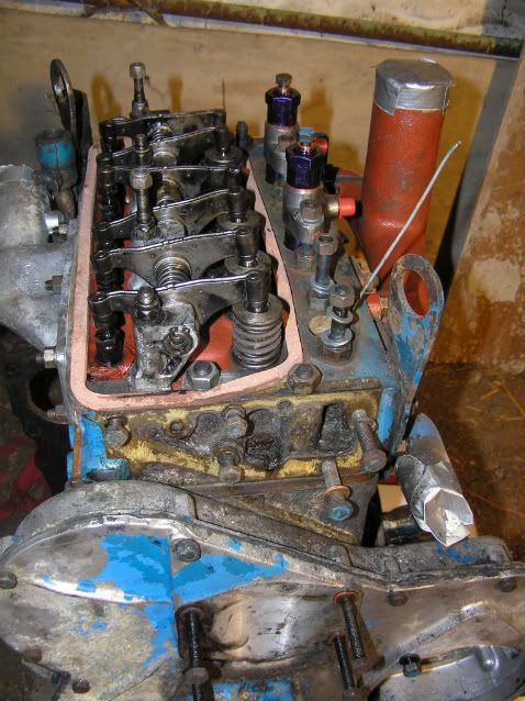
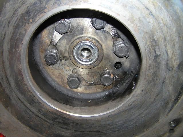
Photo below shows the flywheel in the correct position for TDC, estimated from the clutch housing notch.
Image

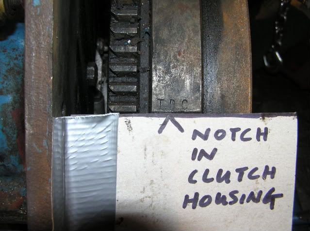
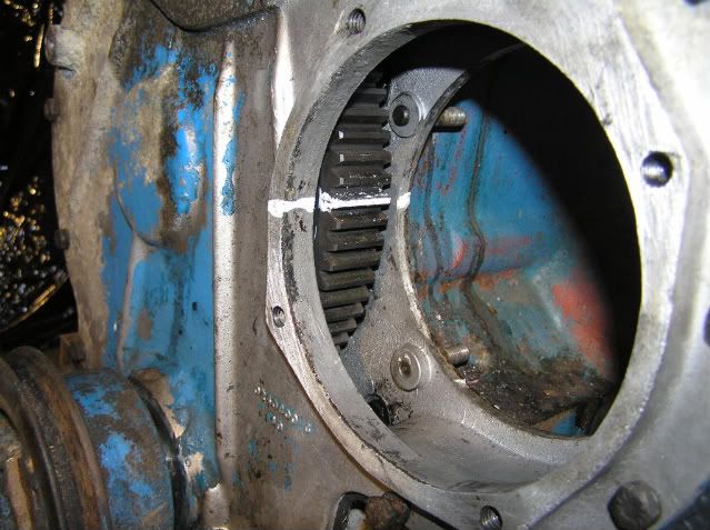
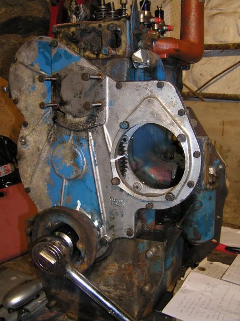
Photo below shows the fuel pump timing line, which also appears to be in the correct position.
Image

I will check with the engine shop when they return from Easter hols as to how the crankshaft could have got moved from TDC, which is the only logical position in which to 'park' an engine after rebuild.

Thanks for the help, without which I couldn't have worked it out :wink:
Ben

Mark
True Blue
Posts: 530
Joined: Thu Apr 17, 2008 2:13 am
Location: Eastern Kentucky

Post by Mark »

Ben,
You have the motor out right now, why don't you take the front cover off and make sure it's in time. That's what I would do, it would be so easy now. If you didn't have a gasket, you could use red silicone for your gasket.
I remember on mine you had to turn the engine over 17 times, I know the IT manual says 18, but it's not always right on many things. I guess that's my two cents worth, hope you check it and make sure, you will sleep better knowing. :lol:
See ya
Mark

When all else fails, get a bigger hammer

Bensdexta
True Blue
Posts: 2666
Joined: Mon Sep 15, 2008 12:59 pm
Location: N Wales

Stopping engine turning

Post by Bensdexta »

Yes I know that's sense, I've just got a new timing cover gasket too. Is there an easy way to stop the engine turning so I can remove the pulley nut - I don't have an impact wrench?
Thanks,
Ben

The Swanndri Guy
True Blue
Posts: 413
Joined: Mon Mar 30, 2009 8:04 am
Location: Near Hampton Downs Motorsport Park,NewZealand

Stop engine turning

Post by The Swanndri Guy »

Ben, in the front pully are there any bolt holes that you could bolt a piece of angle iron on to, using two of the bolt holes?Cut a piece of metal out between the bolt holes so you can still get your 3/4 drive socket onto the pully nut.If the pully holes are not threaded bolt two bolts onto the angle iron, so the exposed thread fits in the pully holes, so you can undo the pully nut. Angle iron needs to be 500mm or longer.Hope this is of some help,Cheers "The Swanndri Guy"

Bensdexta
True Blue
Posts: 2666
Joined: Mon Sep 15, 2008 12:59 pm
Location: N Wales

Post by Bensdexta »

Yes there are 3 threaded holes so I can rig something up as you suggest.
Thanks,
Ben

Mark
True Blue
Posts: 530
Joined: Thu Apr 17, 2008 2:13 am
Location: Eastern Kentucky

Post by Mark »

Ben, if you have an impact, all you have to do is zip the nut off, and your on your way. Now would be a great time to renue the front seal too.
You may need a puller to get the pully off, that's what SG was talking about. These are inexpensive at the local parts store. I have seen them just come right off easy as pie without one.

If you haven't had the head off, now would be a great time to do that too. That way you can besure about TDC, plus head gaskets are inexpensive, and easy to put on.
Last edited by Mark on Sun Apr 19, 2009 2:27 pm, edited 2 times in total.
See ya
Mark

When all else fails, get a bigger hammer

Bensdexta
True Blue
Posts: 2666
Joined: Mon Sep 15, 2008 12:59 pm
Location: N Wales

Post by Bensdexta »

No impact unfortunately :cry:
I can take it to my local mechanic and get him to zip the nut off or use a 'Swanndri' tool.
Thanks for the info,
Ben

Mark
True Blue
Posts: 530
Joined: Thu Apr 17, 2008 2:13 am
Location: Eastern Kentucky

Post by Mark »

Ben, you can still get the nut off without an impact, you can use a pry bar in the teeth of the flywheel to hold it from turning whilst you get the nut off. Get a friend to help you hold the pry bar whilst you take the nut off, and your good to go.

Remember what Brian said about taking your idler pully off to get everything in time. You can also make sure your flywheel is in the right position after you get all the front gears in time, have a gander at it, you may need to reposition it after you get all the front timing spot on.
See ya
Mark

When all else fails, get a bigger hammer

The Swanndri Guy
True Blue
Posts: 413
Joined: Mon Mar 30, 2009 8:04 am
Location: Near Hampton Downs Motorsport Park,NewZealand

Stop engine turning

Post by The Swanndri Guy »

Ben,the purpose of bolting a piece of angle iron to the front pully is so you can undo the pully nut rather than using it as a puller to get the pully off. Always replace the pully seal when you have the pully off even if its not leaking and has not been replaced for decades.Cheers "The Swanndri Guy"

Post Reply