As my previous topics have shown this major isn't giving up and I'm not either.on my last post the PTO was whining so I split the tractor AGAIN! lol and took the primary gear box out to find a lot of issues the primary input shaft rear lock nut was undone and the transmission hand brake was in a shocking condition and the pto drive gear was a little to loose on the shaft . So all of these issues has been sorted and new seals arrived today for the main input shaft but I can't seem to see where to fit the small seal on the input shaft ,has anyone here got a detailed diagram of a live drive primary gearbox so I can see its location ,
Regards Paudie
Diagram for primary gearbox required
Re: Diagram for primary gearbox required
Hello Paudie,
parts suppliers create confusion with their parts descrioption.
There are 3 seals for the intput shaft:
1 normal one for nonen live drive tractors
2 small one, between the two input shafts on livedrive tractors
3 large one, around input shaft in live drive tractors.
If you have the small one (large coin size) and a none live drive tractor, than you can't use it.
If you have a live drive tractor and the input shafts not leaking on the small oil seal, don't replace it. Replacing is tricky and also no warranty for non leaking afterwards.
Rgds
Emiel
Best regards
Emiel
N 1937, E27N 1948, 8N 1949, E27N 1950, E1A Diesel 1953, E1ADKN PP 1956, Dexta 1959, NH Clayson M103 1964
Emiel
N 1937, E27N 1948, 8N 1949, E27N 1950, E1A Diesel 1953, E1ADKN PP 1956, Dexta 1959, NH Clayson M103 1964
Re: Diagram for primary gearbox required
Thanks emiel , it is a live drive type so the small seal dose go somewhere ? but I'm thinking the Same as you and I might just replace the big seal if it is a huge job to remove and replace the small oil seal , I got the hand brake leafs today so ill start that task now.i have got info on the rebuilding of the transmission brake so fingers crossed this will be the final rebuild.
Re: Diagram for primary gearbox required
Rebuilding just the handbrake is no Problem at all.
Just think about checking all bearings while the primary gearbox is out.
Check the following thread:
http://www.fordsontractorpages.nl/phpbb ... f=9&t=5183
I only wanted to rebuild the brake.............
Just think about checking all bearings while the primary gearbox is out.
Check the following thread:
http://www.fordsontractorpages.nl/phpbb ... f=9&t=5183
I only wanted to rebuild the brake.............
Regards Matthias
With County, you can
1959 Power Major
1961 County Super 4 drainagemachine
1963 Super Major
1964 NP Super Major 4x4
1966 County 654
With County, you can
1959 Power Major
1961 County Super 4 drainagemachine
1963 Super Major
1964 NP Super Major 4x4
1966 County 654
Re: Diagram for primary gearbox required
Paudie,
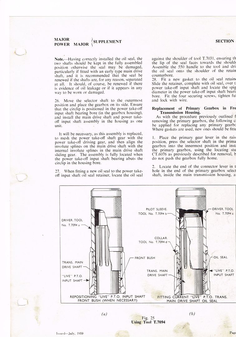
The small seal lives between the outer and the inner input drive shaft. To replace you have to pull the inner shaft out of the outer shaft. Only possible when you've removed the input shaft assembly from the box.
Please download the workshop manual from www.fordson.se to follow the right procedure.
Make sure to work clean, but do not forget it is no rocket science inside your tractor. A little wear on a bearing or gear is not too critical.
Rgds
Emiel
Best regards
Emiel
N 1937, E27N 1948, 8N 1949, E27N 1950, E1A Diesel 1953, E1ADKN PP 1956, Dexta 1959, NH Clayson M103 1964
Emiel
N 1937, E27N 1948, 8N 1949, E27N 1950, E1A Diesel 1953, E1ADKN PP 1956, Dexta 1959, NH Clayson M103 1964
Re: Diagram for primary gearbox required
Hi Paudie.
When you removed the clutch at the start of your "Major" Project , and did the clutch was there oil in the middle of the clutch assembly, or oil on the small input shaft, or any sign now. if so you need to replace that little seal. if it was all dry don't worry until it does start leaking  . As emiel says it's not rocket science with that trans, But you'd be simply over the moon ( mad as heck
 ) if you changed a good seal and the new one leaks. I changed one 15 years ago it was pretty interesting to say the least, by the time the old one was out and the new one was in. I think the just in case I messed up spare seals still on the shelf here somewhere
  .
.
Regards Robert
When you removed the clutch at the start of your "Major" Project
Regards Robert
A Fordson is for life not just for Christmas !.
Re: Diagram for primary gearbox required
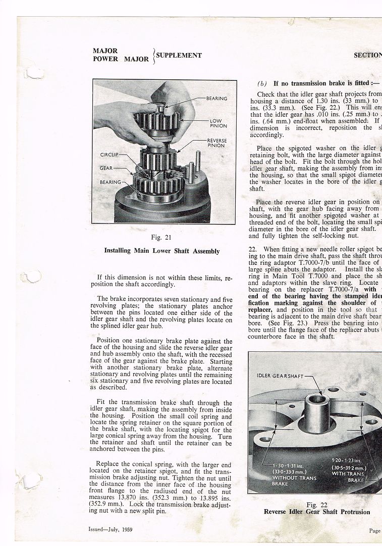
I had a little oil in the bell housing but NOT in the clutch basket and clutch plates. I have tried to research the correct procedure for the handbrake rebuild I have the correct protrusion of the reverse idler gear shaft . I understand that I fit the first stationary wear plate behind the reverse idler gear but is it a revolving wear plate then on the other side of the reverse idler gear and then a stationary wear plate ?. So how many stationary and how many revolving plates are required ?and do I count the last stationary plate ie . The one with the square hole for the Spring .if nay one has link to further info or can take the time to help I'd appreciate it .

Re: Diagram for primary gearbox required
These should help, if you try and set it up without the book you will get good at stripping it down again.
Fordson Tractor Pages, now officially linked to: Fordson Tractor Club of Australia, Ford and Fordson Association and Blue Force.
Brian
Brian
Re: Diagram for primary gearbox required
Thanks Dave for the diagrams , I have all the work carried out now seals and handbrake repaired , I assembled the hand brake as per info given using good second hand parts, the question that I have to ask you ,is it normal to have all the plates and springs fitted correctly and the measurements correct to still have about 5 mm of spare brake idler shaft ( not the reverse idler )
Re: Diagram for primary gearbox required
My gearbox is not installed yet, so I can look toworrow how much mm spare I have.
It could be 5 mmm, even I used new plates.
It could be 5 mmm, even I used new plates.
Regards Matthias
With County, you can
1959 Power Major
1961 County Super 4 drainagemachine
1963 Super Major
1964 NP Super Major 4x4
1966 County 654
With County, you can
1959 Power Major
1961 County Super 4 drainagemachine
1963 Super Major
1964 NP Super Major 4x4
1966 County 654
Re: Diagram for primary gearbox required
Mathias as long as there is ment to be some spare Id think I'd be happy enough to rebuild. I'd love to start bolting the old girl back
Re: Diagram for primary gearbox required
I was in the shop checking the gearbox. It is 4-5 mm spare and the outside plates are springloaded by an inside spring, to avoid friction if handbrake is not engaded.
When I put the primary gearbox back in, I will remeber Brians advice and cut of the first teeth of the loocking mechanism to aviod running the tractor with semi locked handbrake.
When I put the primary gearbox back in, I will remeber Brians advice and cut of the first teeth of the loocking mechanism to aviod running the tractor with semi locked handbrake.
Regards Matthias
With County, you can
1959 Power Major
1961 County Super 4 drainagemachine
1963 Super Major
1964 NP Super Major 4x4
1966 County 654
With County, you can
1959 Power Major
1961 County Super 4 drainagemachine
1963 Super Major
1964 NP Super Major 4x4
1966 County 654
Re: Diagram for primary gearbox required
Well that's all the info I need now thanks everyone and i will keep ye posted as the rebuild is completed . Fingers crossed everybody 
Re: Diagram for primary gearbox required
Ok the gear box is fitted and it all looks good . Here are two tips i had received...cut the hex head of the head bolts from a donor engine and screw them in to the stud holes in the housing they were four inches long and provided great guidance and saved the gasket. I was also tipped off to fit an elastic band around the exposed roller bearings prior to to been fitted to keep them in place while I shoved shook ,and grunted the gear box in to its final destination.thanks again for the help up to now
-
easy.start
- True Blue
- Posts: 55
- Joined: Sun Jun 14, 2015 10:57 pm
- Location: Somerset, UK
Re: Diagram for primary gearbox required
I too will soon remove the gearbox as I have a sneaking suspicion the transmission brake is binding. The gearbox casing gets incredibly hot so much so I couldn't touch it for more than a few seconds after a 12 mile fast drive home from last week's rally and oil has begun leaking from the handbrake lever shaft  . Having never noticed this before I'm assuming my thinking is correct? I'm guessing the transmission brake could simply be removed and gearbox reinstalled without it? Is there a replaceable seal where the lever shaft passes through the casing? Interestingly, as Brian has mentioned numerous times, the lever ratchet has a few of the teeth ground off.
Easy Start (not required for the Fordson)
Re: Diagram for primary gearbox required
I don't recall a seal on the hand brake leaver shaft,I don't think there is one as the oil would be that high up , but if you take the primary gearbox out you should seriously consider re doing the hand brake
-
easy.start
- True Blue
- Posts: 55
- Joined: Sun Jun 14, 2015 10:57 pm
- Location: Somerset, UK
Re: Diagram for primary gearbox required
Re the seal, I wasn't too sure myself as I've searched for one online and can't find one. As pretty much every other seal and gasket is available for Majors I'm assuming maybe there isn't one.
I certainly will be replacing the handbrake components as this does appear to be the cause of my hot gearbox having looked inside now!
I certainly will be replacing the handbrake components as this does appear to be the cause of my hot gearbox having looked inside now!
Easy Start (not required for the Fordson)
Re: Diagram for primary gearbox required
Have you taken the primary gearbox out yet? The advice I got here on this forum was critical to the success of my gearbox re build. especially the tip on cutting the tops of the old head bolts and screwing them in to the housing to use them as guides for reassembly, genius ,
Best of luck
Best of luck
-
easy.start
- True Blue
- Posts: 55
- Joined: Sun Jun 14, 2015 10:57 pm
- Location: Somerset, UK
Re: Diagram for primary gearbox required
The gearbox is now out and been on the floor for an hour  I'll buy the handbrake plates next week and fit it all so should be ready for ploughing in September. One thing that did occur upon extracting the gearbox from the housing was the upper bearing dropped apart. All the rollers dropped out one by one then I hooked out the carrier which is intact. I'm struggling to find this bearing online Any ideas?
Easy Start (not required for the Fordson)
Re: Diagram for primary gearbox required
I'm not sure about where to buy one , but if you got all the bearings and the bearing cage it can be put together and with some greese placed back on the inner bearing race which is on the shaft and fit an elastic band around the cage and bearings to keep them assembled,
Best of luck
Best of luck
Re: Diagram for primary gearbox required
Best regards
Emiel
N 1937, E27N 1948, 8N 1949, E27N 1950, E1A Diesel 1953, E1ADKN PP 1956, Dexta 1959, NH Clayson M103 1964
Emiel
N 1937, E27N 1948, 8N 1949, E27N 1950, E1A Diesel 1953, E1ADKN PP 1956, Dexta 1959, NH Clayson M103 1964
-
easy.start
- True Blue
- Posts: 55
- Joined: Sun Jun 14, 2015 10:57 pm
- Location: Somerset, UK
Re: Diagram for primary gearbox required
Paudie and Emiel, thank you for your replies
Paudie, I thought about what you've suggested and have put it all back together now. Fingers crossed, I can source a new one so I don't have to put it back together then wondering how long it might last! I'm sure they're are plenty of other Majors (and other makes) running about with bearings in shocking condition.
Emiel, it's not the bearing you indicate unfortunately Why is it this bearing is easy to find but the two roller bearings on the shaft above this bearing are not made  Having read Pascals and AdrianNP's previous posts (amongst others no doubt) I'm not the only person who requires them!
Paudie, I thought about what you've suggested and have put it all back together now. Fingers crossed, I can source a new one so I don't have to put it back together then wondering how long it might last! I'm sure they're are plenty of other Majors (and other makes) running about with bearings in shocking condition.
Emiel, it's not the bearing you indicate unfortunately
Easy Start (not required for the Fordson)
-
Fordson 60
- Not Quite Blue Yet
- Posts: 29
- Joined: Mon Aug 29, 2016 7:12 am
- Location: Netherlands Heerenveen
Re: Diagram for primary gearbox required
Hello folks.
I am new here i am reading along for a year
You need the NJ305 and the NJ405 bearings
They are a bit different but wil fit en wil worke fine.
All bearings are metric if You Google the measurements in mm You wil get a bearing number.
Fore example. 20 47 14 in Google wil get You the 6204 bearing
Ronald.
-
easy.start
- True Blue
- Posts: 55
- Joined: Sun Jun 14, 2015 10:57 pm
- Location: Somerset, UK
Re: Diagram for primary gearbox required
Found them
Thank you Ronald for your knowledge and help
Paul
Thank you Ronald for your knowledge and help
Paul
Easy Start (not required for the Fordson)