FORDSON MAJOR LINER REMOVAL

This forum is about the tools you use to service your Fordson tractor AND about the implements you use when out in the field with Ol' Blue.
Post Reply
supermajor61
True Blue
Posts: 74
Joined: Sun Dec 05, 2010 10:38 pm
Location: North Devon

FORDSON MAJOR LINER REMOVAL

Post by supermajor61 »

I have to change the Liners and Pistons on a Fordson Major. First time for me, and i need to make up a removal Tool.
Not seeing any commercial items for sale on or off ebay. Looks like i'll have to make my own tool.
The manual shows the top of the removal tool, but no illustration of the bottom part.

If anybody has one of these tools, could you let me know the dimensions of the bottom part. Thickness, diameter of the threaded hole etc. Will a circular bottom part clear the crankshaft, or do you have to cut down the sides?

Image

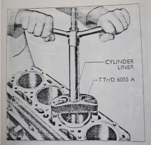
The Fordson tool looks like it can only pull the sleeve an inch or two, will the liner be free after this ?

If anybody has an old sleeve that they could let me have, it would be a big help when i go to the engineering works to have the bottom piece turned.

Dandy Dave
True Blue
Posts: 1859
Joined: Thu Apr 02, 2009 2:49 am
Location: Copake, NY

Re: FORDSON MAJOR LINER REMOVAL

Post by Dandy Dave »

You only have to move the liners a little way and then they will pull out easily with your hand. I have a home built sleeve puller myself that I have modified though the years to pull sleeves out of a variety of engines that I have rebuilt. I used a piece of well casing pipe, which is larger than the sleeve, to rest against the block, and a piece of threaded rod to the bottom with a piece of steel to pull against. Some times I have turned a plug on a lathe to fit the bottom of the sleeve. It is a simple device that works well. Dandy Dave
Have a Fordsonful day Folks!

1960 Fordson Power Major

Roadless63
True Blue
Posts: 261
Joined: Tue May 06, 2008 10:49 pm
Location: Derby/Hants

Re: FORDSON MAJOR LINER REMOVAL

Post by Roadless63 »

Hi, I have one of these tools, it is a disc with a slot cut through the middle, this is attached to the centre rod and allows the disc to flip up inline with the rod to allow it to be slid down the bore. The outer edges have been machined flat either side to give more clearance. It is reversible for 2 size liners, (I think 1 is 100mm but cant quite remember) with a small step machined in to locate into the bottom of the liner. The threaded part is at the top.
It is easy to make a similar version more simply, I did this for a fergy engine, turn up a disc a few mm wider than the bore, and a lip just undersize to locate in the bore. Thickness of disc around 15mm should be ok. Drill and tap centre to a suitable size eg m12 or m14. Use long piece of threaded bar and a stout piece of steel bridged accross top of liner, spaced up either side to allow clearnance for the liner to lift a few inches. A couple of locknuts together and hey presto turn the threaded bar and up comes the liner.
Also worth noting that if work being carried out with head off and crank being turned it is good practice to lock liners down to prevent them becoming dislodged and losing their seal.

Post Reply