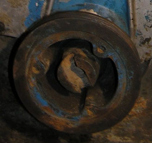
I have just checked the size and a 1.11/16" AF socket is a loose fit on the nut but , I think it is as close as you can get. 1.5/8" is too small and 1.3/4" is too large. I measured the nut as 1.82" AF!
I have just checked the size and a 1.11/16" AF socket is a loose fit on the nut but , I think it is as close as you can get. 1.5/8" is too small and 1.3/4" is too large. I measured the nut as 1.82" AF!
Gerald
Gerald,
Many thanks most helpful - I guessed it must be 1-11/16", which I don't have! This is 42.863mm, so I don't think your 1.82" AF can be right (46.23mm)?
I should have written the measurement down as I have left a 6 out, it should have been 1.682"! I tried a 42 mm socket but it was too small and as far as I know you cannot get a 43 mm socket.
The nut may well be a Whitworth size, unfortunately I can't find my tables to verify this.
Tubal Cain wrote:I should have written the measurement down as I have left a 6 out, it should have been 1.682"! I tried a 42 mm socket but it was too small and as far as I know you cannot get a 43 mm socket.
Gerald,
Many thanks for trying the 42mm - much appreciated.
So 1.11/16" it is.
Any preference for a Hex or a 12 point?
Thanks again,
Ben
Just tolerance variations on sockets and nuts.
1 5/8" is only 1/16" different to 1 11/16" or 0.0625" (1.59mm).
If the socket is made on top size of the manufacturing tolerance and the original nut was made on bottom size, plus allowing a little more 'loss' for rust and wear over the years, it is likely 'to go'.
Put into more 'understandable' perspectives, the difference between the two sizes is only the thickness of 20 human hairs (10 on each side).
A typical manufacturing tolerance for that type of nut, at that time, which is actually 'drop forged' or 'swaged', not machined, would be plus or minus 0.025" from 'nominal size'.
I have not checked the 'specs' in the manual, but I would be very surprised in the 'nominal design size' for the nut was not actually specified as 1 5/8" and that corrosion, over the years, made it bigger.
'Normal practice', at that time, would be to produce the 'forming tool' at 'Nominal size - 0.025" (bottom permissable size) then just keep using it to produce until, through normal wear from production, it became 'Nominal size + 0.025" before you replaced it.
Cheaper to make - Produces more before replacement needed.
It is very unusual, back in those days, for designers to specify the AF size (across flats) to be to the nearest 1/16 of an inch, when 1/8" was easier (and cheaper) to achieve on a feature that had 'no operational effect'.
Of course I could be wrong, Ford in particular over recent years, have become renown for introducing changes, just to ensure that you 'need' to use their 'agents' instead of DIY. 'Rocker Cover' screws are a typical example. Started off as common 'AF hex heads' needing only spanners, then changed to needing hexagon socket 'Allen keys', now require 'torxque drivers', then put a 'pip' in the middle to change the type of torxque driver needed but, back in those days, the idea was 'make it simple and cheap for Joe Public to do himself with standard tools' because it helped sales.
Mike,
Many thanks for the explanation. So all our tractors are probably individuals, built before the days of computers and numerical controlled manufacturing. Reminds me of old aeroplanes which were all different, hence when they came to re-wing the Nimrod maritime patrol planes, the new computer-manufactured wings wouldn't fit
All the best,
Ben
Not so much 'individuals', just 'slightly more variable' than things are today, for example...
It was common practice that if a crank journal was ground up to 0.005" below the tolerance, instead of scrapping it, it would be used with 'special' marked, undersize bearing shells (Oh! the memories of dads old 'sit up and beg' Ford Pop )
NC and CNC? Plug-Board capstan lathes were just appearing as our 'old girls' were finishing production.
So, you heard about the Nimrod 'main planes' then? A nightmare I got slightly involved with, 'many moons ago'. The problems with replacement 'fuel flaps' were even funnier. They are 'gravity flaps' to stop the fuel 'sloshing about' inside the main planes (wings) during mid-air manouvering.
New ones were produced, with a flat face, for a good 'gravity seal' then it was found that the mating casting faces had never been flat and the original 'flaps' had been 'blued' and 'hand fettled' to seal.